I wrote this up as an article which was published in Make: magazine: Hacking R/C Power Outlets
Switching mains appliances from your computer or microcontroller project is not difficult in theory, but achieving it without turning your home into a potential deathtrap can be tricky! This project describes modifying a remote controlled power outlet system to provide a safe and economical way to switch appliances wirelessly around your home. By wiring a small microcontroller board inside the remote control, you can provide a USB interface that will allow the outlets to be switched from a computer. As an added bonus, understanding the system’s wireless protocol gives you the potential of expanding it to switch more than just the supplied outlets.
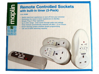
I had the idea for this project after buying a set of remote controlled power outlets from my local electronics store. There are quite a few of these systems available now, some with individual outlet units, four-way extensions, and even outlets housed in waterproof casings for installing outside. The set I bought (shown in figure 1) consisted of three separate outlet units and a remote control. Obviously you’ll want to use a system which has the appropriate power connectors and ratings for your country, so see what is available locally (the ones shown here are for the UK). They all generally work on the same principle – you plug the outlet unit into a regular power outlet, with the appliance to be controlled plugged through the unit. Power to the appliance can then be switched on and off using the remote control. My remote had four sets of “on” and “off” buttons, allowing each supplied outlet to be controlled individually, with an extra set of buttons to command all outlets at once.
One of the really nice things about this project is that you don’t need to modify the power outlet units at all – these remain safely intact together with all their approvals (FCC, CE, etc). All that you need to modify is the remote control, which is battery powered.
The transmitter communicates with the outlet units using radio signals, so there is no need to point it at an outlet in order to control it like you would with an infra-red remote. This makes it ideal if you’ve got outlets which are difficult to access, such as behind a TV or under a desk. In fact the instructions state that the remote will work up to 25 meters away. Each outlet unit can be assigned to any of the buttons on the remote by pressing “learn” on the outlet unit then pressing the button you want to assign on the remote. You can even have more than one outlet controlled by the same button if you wish. The units I bought also have a timer feature, so they can be made to automatically switch off after 1, 2 or 3 hours.
I was impressed by this system and was keen to expand it to control more of my appliances; however, I wasn’t sure whether more than one set could be used without causing problems (strangely, the instructions did not mention this). One thing I did happen to notice is that if you disconnected the remote’s battery for a while and then reconnected it, the outlet units would no longer respond to the remote without having to go through the learning process again. The only explanation I could think of for this is that the remote must generate a unique or random identifier when it powers up, which the outlet units remember during the learning process. This is a very good sign as it means that two or more sets could be used in the same area without interference, provided that their remotes were using different identifiers. This would also mean that similar devices being used nearby would be unlikely to cause problems.
So far so good, except that you’d need to use a separate remote for every set of three units, which could soon get out of hand. For example if you wanted 30 units in your house (quite a lot, but not beyond imagination) you would need 10 separate remotes to be able to control them all! What I really wanted was to be able to control the units from a computer, as this would give me lots of flexibility, for example, I could switch appliances from over the internet, or at certain times of the day by writing a program.
With this in mind I opened up the remote control unit by removing the four screws, to reveal a circuit board housing button pads, an Elan EM78P153SNJ microcontroller, a +5v regulator and an LED (see figure 2). The circuit board also had unused contact pads for another set of control buttons, so this could potentially allow an additional unit to be controlled. Underneath this board sat another board housing the radio transmitter circuit and antenna.
I decided that the USB Bit Whacker board from SparkFun Electronics would be ideal to help me with this project as it has a USB connection to communicate with a computer, and it is small enough to fit inside the remote control case. A simple approach would be to connect the Bit Whacker’s port pins to the button inputs, simulating buttons being pressed, although this would still have all the limitations of the original remote, i.e. only being able to control three individual units. I decided instead to try and intercept the data signals being sent from the remote’s microcontroller to the radio transmitter circuit on the board underneath. If I could decode these signals then I could also generate my own, and potentially control more devices if the protocol allowed.
The yellow dotted line in figure 3 shows the data connection I wanted to intercept. I found that the easiest point to do this was where the connection passed on the underside of the board via a wire link (this is a single-sided circuit board). I simply removed the wire link and soldered wires to each endpoint, running them to available port pins on the Bit Whacker board. I also connected ground and 5v power from the Bit Whacker to the board (taking care to connect to the 5v output side of the voltage regulator), thereby enabling the remote to be powered over USB.
I found that the Bit Whacker board could be glued inside the lid at the rear of the remote, with a rectangular hole cut out to allow the USB cable to be connected. Figure 4 shows everything in place before I put the remote back together.
The yellow wire is the output from the Bit Whacker to the transmitter circuit (connected to Bit Whacker pin B0), which will allow data signals generated by the Bit Whacker to be transmitted. The pink wire is the original data signal from the remote’s microcontroller (connected to pin Bit Whacker pin B1), which will allow these data signals to be intercepted when buttons are pressed on the remote.
Once the modifications to the remote were complete (shown in figures 5 and 6), I turned to the software side of things. It was necessary to determine what the signals sent to the radio transmitter looked like, so that that similar signals could be generated. This could be done using the Bit Whacker board.
The Bit Whacker is a fantastically simple but versatile little board, consisting of a PIC18 microcontroller plus a few supporting components: an oscillator, reset and program buttons, status LEDs and a USB socket. It comes already programmed with firmware based on the Microchip USB framework that makes the device appear as a serial port (the firmware can also be updated over USB if desired). It can be controlled by sending text-based commands using a terminal program such as Hyperterminal, or by writing your own program which talks to the serial port. There is a full set of commands available to control the port pins, and various other functionality offered by the device.
I realized that because the signal from the remote’s microcontroller is likely to be digital (on or off), instead of trying to sample it at regular intervals, it would be far more efficient to record the time between state changes. This was necessary to allow the signal to be determined accurately, as the PIC’s memory was not large enough to store very many samples. I needed to make some modifications to the Bit Whacker’s firmware to do this, adding a new command which uses one of the PIC’s timers to count the number of clock ticks, recording and resetting the value whenever the input pin changes.
Using this technique, I was able to determine an accurate picture of the waveform generated by the remote. I found that each button press generated a series of pulses: a long start pulse; followed by a fixed pattern of 25 pulses; followed by 64 pulses with short and long gaps in between, encoding 8 bytes of data. The start of such a sequence is depicted in figure 7.

The start pulse was 3.6ms, and subsequent pulses were 0.5ms. The long gaps were 0.8ms, and represented binary “0”, and the short gaps were 0.5ms and represented binary “1”. I determined that the 8 bytes of data in each packet encoded a 2 byte identifier (which the remote randomly picked when it powered up) and a command that specified the action to perform (e.g. switch unit “A” on). Also encoded was a single byte counter value, which was incremented for each command sent. This had an obfuscating effect, and resulted in different data being sent every time, even if the same button was pressed. There was no serious encryption going on here – the point of this encoding seemed to be to reduce the possibility of the outlet units being triggered by random noise or interference from other systems – a form of cyclic redundancy check. The outlet units did not actually check the counter value, and responded to data encoded using the same counter value repeatedly.
The way in which the information was encoded was not as simple as I had anticipated and required some detective work to figure out. Actually, decoding the data was fairly simple as the data was encoded as the difference between pairs of bytes, and therefore only required a subtraction to decode. However, encoding was more complex because there were various relationships between the absolute values of the 8 encoded bytes that had to be present in order for the outlet unit to accept the commands.
I named the 8 encoded bytes X1, X2, X3, X4, Y1, Y2, Y3, Y4; and the 4 decoded bytes Z1, Z2, Z3, Z4. Of the decoded bytes, Z1 was the counter, Z3 was the command, and Z2 and Z4 made up the 2 byte identifier. Through some investigative work, I was able to determine the following formulae for decoding and encoding the data:
Decoding:
Z1 = X1 - Y1
Z2 = X2 - Y2
Z3 = X3 - Y3
Z4 = X4 - Y4
Encoding:
Y1 = (4 * Z2) - (3 * Z1) + (2 * Z4) + Z3 + 97
X1 = Z1 + Y1
Y2 = Y1 + Z4 - 188
X2 = Z2 + Y2
X3 = X2 - 19
Y3 = X3 - Z3
X4 = X3 + Z4 - 104
Y4 = X4 - Z4
Note that all these operations are single byte (mod 256) – meaning that the value wraps around to 0 when incremented past 255, which is the maximum value that can be stored in a single byte.
The identifier determines the set of outlet units to which the command applies. This is a 16 bit value, and therefore allows up to 65536 sets of outlet units to be addressed.
The command can take one of several possible values, most of which correspond to buttons on the remote control. Through testing, I also found several other command values which the outlet units responded to, most notably 0x64, which appeared to affect only units which were currently off, switching them on for a brief moment then off again. Below is a complete list of commands that I was able to determine:
| Command | Action |
|---|---|
| 0x03 | C off |
| 0x04 | C on |
| 0x13 | D off (generated by unused button pad on the remote) |
| 0x14 | D on (generated by unused button pad on the remote) |
| 0x23 | All off |
| 0x24 | All on |
| 0x63 | All off (no button) |
| 0x64 | Pulse all off units on momentarily, then off again (no button) |
| 0xe3 | A off |
| 0xe4 | A on |
| 0xf3 | B off |
| 0xf4 | B on |
There are commands to independently switch up to four units, so given the number of possible identifiers, this will allow 262144 individual outlets to be controlled!
The information I obtained enabled me to intercept and decode data from the remote control, and to encode and inject my own data to be transmitted to the outlet units. I made some further modifications to the Bit Whacker firmware in order to do this, which generated waveforms comparable with those produced by the remote using the timing information determined earlier.
The final part of the project was to write a computer application to control the units, as it was not very convenient having to enter commands into a serial console. Rather than writing a fancy graphical application, I decided that a simple command line program would be better in many ways. Firstly, it would be simpler; making it less prone to errors and easier to port (I wanted to run it on both Linux and Windows); secondly, it would be possible to create shortcuts (e.g. on the desktop or a toolbar) to control particular units; and thirdly, it would allow automation by calling the program from a script or batch file, or from the task scheduler (on Windows) or cron (on Linux), allowing units to be switched at preset times or in response to certain events.
I found that opening and closing the USB serial port to send each command was problematic, and would fail if more than one program was trying to access it simultaneously. I decided the best solution was to split the program into two parts – a server which runs all the time in the background, holding the serial port open and managing the flow of commands to it; and a command line client which sends commands to the server. I decided to use TCP/IP sockets as the communication method, which had the added benefit that the server and client could run on different machines provided they were connected through a network.
The screenshot in figure 8 shows the server running (indicated by the socket icon in the system tray), with several shortcuts that I have made to the command line client in order to switch various appliances on and off. To create the toolbar at the bottom, I right clicked and selected “new toolbar” from the toolbar menu, and selected an empty directory. When creating shortcuts, I entered the required command-line arguments after the program name in the “target” box, which consisted of the device identifier (0-65535), button (a, b, c, d or all) and state (on or off). I also selected an appropriate icon using the “change icon” button (I created these icons myself using Inkscape).
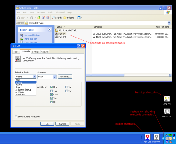
It also shows some scheduled tasks, which I made by dragging the desired shortcuts I’d already created into the scheduled tasks window (this can be found under control panel). There are quite a variety of scheduling options, but if that isn’t flexible enough, the command can also be called from a batch file or scripting language of your choice (I’d recommend Perl).
There is a great deal of potential in these remote outlet systems; their availability and relatively low cost makes them ideal for use in electronic projects where you need the ability to switch mains appliances. The benefits include flexibility (allowing the controlled appliances to be moved and plugged in wherever is most convenient) and safety (your project needs no physical connection to the appliance or mains wiring). This project highlights just one way in which they can be utilized, and I have tried to keep my modifications as general as possible so they may be useful to others. Hopefully I have shown how easy it can be to interface with these systems, and how, by understanding a bit about how they work, you can make them work the way you want them to!