Impressed with a remote controlled power outlet system that I had bought, I undertook quite an extensive project to discover exactly how it worked, and how it could be modified to allow any number of power outlets to be controlled from a computer.

From: Maplin (order code N19GN)
Link: Remote Controlled Socket Set with built-in Timer 3-Pack (no longer working)
Price: UKP 19.99 (often discounted to UKP 12.99)
Outlet units
- Info sticker:
Remote control socket
Model no: N19GN
Rated voltate: AC240V/50Hz
Rated power: 3120W
Frequency: 433.92 MHz
- 2x pushbuttons – (“Learn”, “on/off”)
- 4-way slide switch for timer setting – (off, 1h, 2h, 3h)
- Red status LED – indicates when appliance is switched on
- 3 pin 13A UK mains plug on back
- 3 pin 13A UK mains socket on front
Disassembly
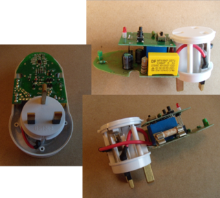
- 5x “Y” type security screws – easily undone with a flat terminal-type screwdriver!
- 1x smaller pozi screw at top
- 4x small pozi screws fixing control board to upper half of case
- 2x loose button inserts and 1x slide switch insert in upper half of case
Main board
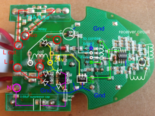
- 13A mains type fuse
- Relay “Songle SLA-24VDC-SL-A (30A 250VA)”
- Supressor cap “DF MPX/MKP 0.68uF”
- 78L05 [SMT] regulator
- 4x MT [SMT] diodes as bridge rectifier
- 1x MT [SMT] diode across relay coil
- LM358 [SOIC-8] op amp in receiver circuit
- 2×4 100mil socket to connect to control board
PSU circuit is similar to this.
RF Receiver circuit is similar to this.
Control board
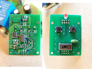
- Elan EM78P153SNJ [SOIC-14] 8-bit microcontroller
- BL24C02 [SOIC-8 150mil] 2Kbit I2C serial EEPROM
- 4.0MHz resonator [2 terminal TH]
- 1×4 100mil extended headers to connect to main board
Space for additional 1×4 100mil connector with same pinout as main board connector at opposite end of board, possibly a test connector?
Remote control
- Info sticker:
Remote control socket
Frequency: 433.92 MHz
- 9x pushbuttons – (“reset”, “A on”, “A off”, “B on”, “B off”, “C on”, “C off”, “All on”, “All off”)
- Red status LED – indicates when transmitting data
- Battery compartment underneath for 9v PP3 battery
Disassembly
- 4x pozi screws
- 4x smaller pozi screws fixing control board to posts on lower half of case
- 8x loose button inserts of various sizes in upper half of case
Control board
- Elan EM78P153SNJ [SOIC-14] 8-bit microcontroller
- Red status LED
- 5v regulator [3 terminal TH] (note: the pinout indicates this is NOT a 7805-type device)
- PP3 9v battery clip connector
- PCB has unfilled component pads that would accomodate a SOIC-8 IC, possibly a serial EEPROM?
- 3 pins connect control board to radio board underneath, these carry Gnd, +9v, and data signal to transmit from MCU.
- The dotted yellow line annotated on the above image shows the data signal path from the MCU to the transmitter circuit.
Radio board
- 433.92 MHz RF transmitter module [3 terminal TH]
- 2x 2SC3356 [SOT-23] NPN transistor
- Large track around approx 2/3 of the board forms an aerial.
Communication protocol
Decoding
By making a connection to the data line between the MCU and the radio transmitter circuit in the remote control, I was able to sample the data being sent. The following is a section of these data samples:

By examining this and several other sets of samples, I found that the protocol uses data packets consisting of a 3.6ms start pulse, followed by a pattern of 89 pulses, each of 0.5ms duration. The data is encoded in binary and represented by two different durations between these pulses – a 0.5ms gap representing one state, and a 0.8ms gap representing another. I also noticed that the first 25 gaps are always the same – 24 long gaps, followed by 1 short gap. This pattern, together with the start pulse, are probably designed to enable the receiver to detect the start of a packet and prepare to receive the data which follows.

The remaining 64 gaps encode the data, which appears to be obfuscated and/or encrypted in some way, as pressing the same button on the remote control results in different patterns being sent. For example, the following patterns were produced by pressing the “A on” button five times, followed by the “A off” button five times (here “-” represents a long gap, and “x” represents short gap):
A on:  -x--x--xxxx-x-x-xx-x-xxx-xx--x-x----x-xx-x---x-xxxxx--xx-xx-xxxx
       -x----xxxxx----xxx--xxx--x-xxx--------x---xxxx--xxx-x-x--xx--xx-
       --xxxxxxxx-xx-xxxx--x----x-x-xx-xxxxxx----xx-xx-xxx--x---xx-----
       --xxx-xxxx-x-x-xxx----x--x-x----xxxx-xx---xx----xx-xxxx--x-xx-x-
       --xx-xxxxx--xxxxx-xxxx---x--x-x-xxxx------x-x-x-xx-xx----x-x-x--

A off: --xx-x--xx--x-xxx-xxx----x---xx-xxx-xx----x--xx-xx-x-x-x-x-x----
       --xx----xx---x-xx-xx--x--x------xxx--xx---x-----xx--xxxx-x--x-x-
       --x-xx--x-xxxxxxx-x-xx----xxx-x-xxx--------xx-x-xx--x--x-x---x--
       --x-x---x-xxx--xx-x--xx---xx-x--xx-xx-x----x-x--xx----xx--xxxxx-
       --x--x--x-xx--xxx-x-------x-xxx-xx-x-x------xxx-x-xxxx-x--xxx---
By observing more data, I was able to observe patterns which appear to be counting in binary, though not in a simple, sequential manner. By observing how these patterns were changing, I could infer that these 64 gaps represented 8 octets, and as the first gaps were changing less than the later gaps in each octet, this suggested the octets are transmitted MSB first, with the long pulses representing binary zeros, and the short pulses representing binary ones. This allowed me to transform the above patterns into binary, and then into a hexadecimal representation, the results of which are shown below:
       X1 X2 X3 X4 Y1 Y2 Y3 Y4
A on:  49 ea d7 65 0b 45 f3 6f
       43 e1 ce 5c 02 3c ea 66
       3f db c8 56 fc 36 e4 60
       3b d5 c2 50 f6 30 de 5a
       37 cf bc 4a f0 2a d8 54

A off: 34 cb b8 46 ec 26 d5 50
       30 c5 b2 40 e6 20 cf 4a
       2c bf ac 3a e0 1a c9 44
       28 b9 a6 34 da 14 c3 3e
       24 b3 a0 2e d4 0e bd 38
Initial observations are that this does not appear to show any obvious pattern, other than a general counting-down trend. However, you will notice that I have labeled each octet X1, X2, X3, X4, Y1, Y2, Y3 Y4 respectively. The reason for this that I noticed that if you subtract each Y from each corresponding X value modulo 256 (as an 8-bit MCU would do) you get the following 4 octets for each of the above, which I have labeled Z1-Z4:
                                 (Zn = Xn - Yn)
       X1 X2 X3 X4 Y1 Y2 Y3 Y4    Z1 Z2 Z3 Z4
A on:  49 ea d7 65 0b 45 f3 6f    3e a5 e4 f6
       43 e1 ce 5c 02 3c ea 66    41 a5 e4 f6
       3f db c8 56 fc 36 e4 60    43 a5 e4 f6
       3b d5 c2 50 f6 30 de 5a    45 a5 e4 f6
       37 cf bc 4a f0 2a d8 54    47 a5 e4 f6

A off: 34 cb b8 46 ec 26 d5 50    48 a5 e3 f6
       30 c5 b2 40 e6 20 cf 4a    4a a5 e3 f6
       2c bf ac 3a e0 1a c9 44    4c a5 e3 f6
       28 b9 a6 34 da 14 c3 3e    4e a5 e3 f6
       24 b3 a0 2e d4 0e bd 38    50 a5 e3 f6
Now we can see a pattern emerging – the Z2 and Z4 values are the same for all packets, and the Z3 value changes according to the command. After some more investigations, I was able to determine what each of these octets represents:
| Octet | Meaning |
|---|---|
| Z1 | A counter, which is incremented by at least one for every packet sent. The purpose of this seems to be to obfuscate the data, ensuring that different values are sent when the same button is pressed repeatedly. Note that the outlet units seem to ignore this value, so it does not prevent anyone recording and replaying data to re-send the command – the command will still be accepted by the outlet unit even if the counter value is the same as the previous command. Note that the transmitter sometimes sends two or more commands in response to a single button press, (possibly depending on how long the button is held down for?). This may account for the sequence of Z1 values seen in the above example, as I had only captured the first complete data packet for each button press. |
| Z2 | The first part of a 16-bit identifier for the transmitter. This appears to be randomly generated when power is first applied (the LED flashes to indicate this is happening). Disconnecting the battery for an extended period of time will cause it to be reset. |
| Z3 | The command being sent. Valid commands are as follows: 0x03 = Unit C OFF 0x04 = Unit C ON 0x13 = Unit D OFF 0x14 = Unit D ON 0x23 = All units OFF 0x24 = All units ON 0x63 = All units OFF 0x64 = Pulse all currently OFF units ON momentarily, then OFF again 0xe3 = Unit A OFF 0xe4 = Uint A ON 0xf3 = Unit B OFF 0xf4 = Unit B ON In other words, the lower nybble seems to determine the ON or OFF state, and the upper nybble determines the unit(s) to address. No other combinations apart from the above were found to be valid. Notice that there are commands to allow 4 units with the same ID to be switched – the commands to switch unit D are generated by shorting the hidden button pads on the remote control PCB. No buttons generate the 0x63 and 0x64 commands, this is undocumented functionality, although I’m not really sure how useful this is! |
| Z4 | The second part of a 16-bit identifier for the transmitter (see Z2). |
Encoding
The next challenge was to be able to convert my own data (Z1-Z4) into an encoded representation (X1-X4,Y1-Y4) that would be accepted by the outlet units. There appeared to be some additional relationship between the Z data and the X,Y representation that had to be satisfied in order for the outlet units to accept the data packets as being valid.
After spending a while looking at patterns in the differences between subsequent bytes, and trying some packets to see which would be accepted by the outlet units, I came up with the following code for encoding Z data into X,Y for transmission:
Y1 = 0x61 + (4 * Z2) - (3 * Z1) + (2 * Z4) + Z3
X1 = Z1 + Y1
Y2 = Y1 - 0xBC + Z4
X2 = Z2 + Y2
X3 = X2 - 0x13
Y3 = X3 - Z3
X4 = X3 - 0x68 + Z4
Y4 = X4 - Z4
(Note that these are all unsigned byte operations, i.e. mod 256)
The above allows us to synthesise any ID and command combination, which can then be sent to the transmitter circuit. As the protocol uses a 16-bit identifier, and there are commands to control up to four units with the same identifier, this gives us the possibility of controlling up to 2^16 * 4 = 262144 individual units!