I’ve decided to make a robot!
I think its something everyone should do at some point, but to be honest, its never particularly appealed to me before. Now with the Raspberry Pi, I can make one that runs Linux, which is slightly more appealing.
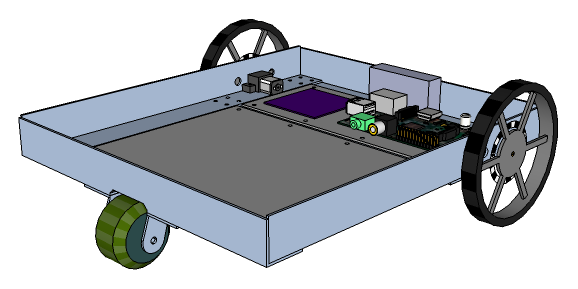
I started by sketching out some ideas for the basic structure – something very simple to start with, but would allow me to add on bits later perhaps. I don’t have much time to spend building it, so I chose to base the design around parts that can be obtained easily and adapted as required. The chassis will be based on aluminium corner profiles, which is easy to work with and will provide a sturdy platform when bolted together to form a rectangle. My design has two powered 90mm wheels, one on each side of the chassis, and a single unpowered 40mm omni-wheel at the front. This will allow the robot to move forwards and backwards by driving the wheels together, and allow turning by driving them at different speeds (or in opposite directions for very tight turns). The use of the omni-wheel at the front is to accommodate the sideways movement when turning.
I went on to draw it out properly in SketchUp, which allowed me to work out the exact dimensions taking into account the motors, wheels, etc that I wanted to use. I selected to use a micro metal gearmotor to drive each wheel – these are tiny motors with a gearbox attached, and are available in different gear ratios. Using the 100:1 ratio gearmotor, which runs at 120rpm, will move the robot at 0.57m/s (~2 km/h) when used with 90mm wheels.
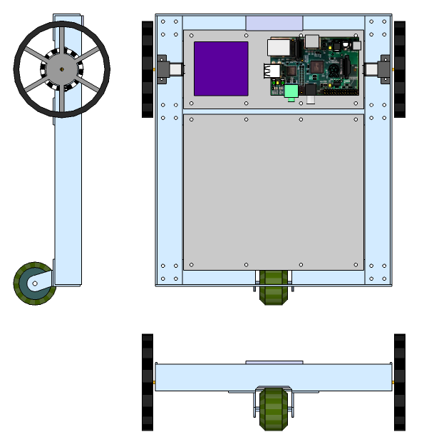
The Raspberry Pi and other control electronics will be mounted on a platform placed in between the two powered wheels. Batteries will be mounted around the edge of the chassis, as required to distribute the weight. The remaining space within the chassis can then be used to accommodate various payload modules, to be designed later. Some ideas I had were a robot arm, movable camera, vacuum cleaner and a pen for drawing on the ground.
I had hoped to be able to buy a module which would allow me to control the two motors using PWM, based on feedback from a pair of photoreflective sensors, aimed at a ring of alternating black and white bands on each wheel. But, as I couldn’t find such a thing, I decided to make my own.
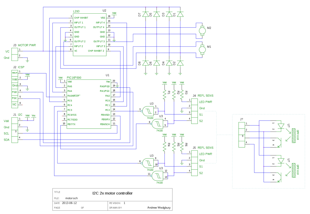
I wanted the motor module to take responsibility for driving the motors, using PWM to vary the power applied to each motor based on feedback from the sensors to maintain the speed and direction of each wheel. The Raspberry Pi will send commands to the motor module via an I²C connection allowing the desired speed and direction of each motor to be set. With all this in mind, I decided to use a PIC16F690 microcontroller, along with a L293 (or compatible) dual H-bridge motor driver and some Schmitt trigger gates to handle the sensor inputs. I designed the following circuit using gschem (part of the gEDA suite):
I then went ahead and designed a PCB for this schematic, using the gEDA PCB layout tool. After a bit of shuffling about I came up with the following 2-layer board, measuring 2×2 inches:
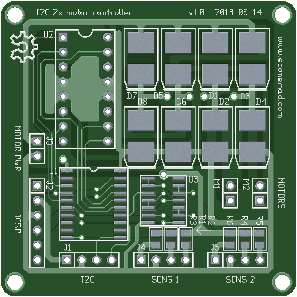
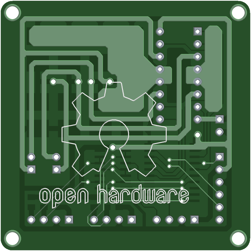
I chose to use SMD components where possible to minimize the size of the board. A lot of the board is taken up with the large DO-214 footprints required for the eight flyback diodes. I couldn’t decide whether to include these or not, since some versions of the H-bridge IC have these included (e.g. the L293D), but in the end I decided to leave space for them on the board just in case. I also included the OSHW logo, since I intend to make the schematics freely available for anyone to use.
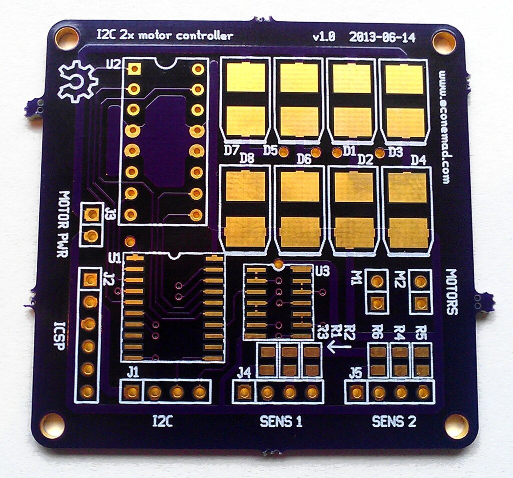
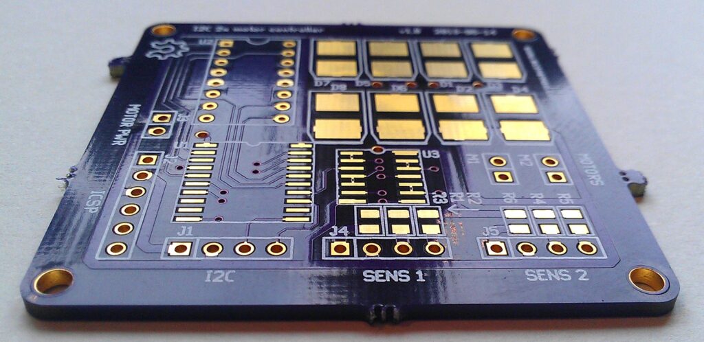
Finally, I exported the PCB layouts to the standard Gerber format and sent them off to OSH Park for fabrication.
I got three copies of the same board (and a sticker), which arrived in a nice purple envelope:
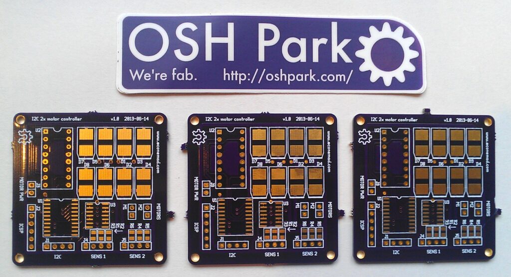
I’m very impressed with the quality of the boards and the price – its really not worth trying to make them yourself any more.
Next I will be soldering on the components and testing it out. Although I also need to write some firmware for the onboard PIC processor to make it do what I want, which will be the difficult part.